Timers and Interrupts on the PIC32MZ post
Using timers on the PIC32MZ
Timers overview
Timers are one of the things that the PIC32MZ does really well. It has 9 independent 16-bit timers, some of which can be combined to make 32-bit timers. It also has an awesome Output Compare module, which I'll cover next time with Pulse Width Modulation (PWM). All the timers work as follows:
- On every PBCLK3 clock cycle, the value of the timer counter (TMR) is increased.
- This value is compared to the Period Register (PR) value.
- If the value is bigger or equal to PR, an interrupt is generated and the value of the counter is reset.
From this it can be seen that the most important registers for us are the Timer Register (TMR) and Period Register (PR).
IMPORANT: The timers on the PIC32MZ are all controlled by Peripheral Bus Clock 3 (PBCLK3), so whatever you set that to will directly affect all the timers.
<TL;DR>
16-bit? 32-bit? As you likely know, 16-bit unsigned variables can store a maximum value of 2^16 - 1, or 65535, and 32-bit unsigned variables can store 2^32 -1, or 4,294,967,295 (~4 billion). This can become very important when we are either wanting super precision or extremely low frequency timers, as I will show later.
For 32-bit timers, timers 2 and 3, timers 4 and 5, timers 6 and 7 and timers 8 and 9 can be combined to form the 32-bit timers.
</TL;DR>
Calculating the value to put into the Period Register (PR)
Say for example we want to generate a timer that runs at 10kHz. We calculate the period like this:
Period Register = Peripheral Bus Clock 3 Frequency / 10000.
In my examples, PBCLK3 runs at 100MHz, so this gives us:
PR = 100,000,000 / 10,000 = 10,000.
10000 is much smaller than the maximum value of 65,535, so no problems there.
Now let's try that again but at 1kHz:
PR = 100,000,000 / 1,000 = 100,000.
Uh oh. 100,000 cannot fit into 65,535 so we're going to have the timer running at a frequency we don't expect. What can we do about this? Well, two things:
- Change over to a 32-bit timer, which is overkill of the highest degree, OR
- Use the timer's built-in pre-scaler
Using the pre-scaler
OK before I start this section, be careful which timer number you use. Timer 1 has some differences to Timers 2 to 9 and as such I recommend using Timers 2 to 9 unless you know what you're doing. In my example today I'll be using Timer 2. Anyway, the timer has a kind of built-in divider circuit called a pre-scaler. It works like this:
- On every PBCLK3 clock cycle, the value of an internal counter is increased.
- This value is compared to pre-scaler setting (TCKPS) in the Timer 2 Control Register (T2CON).
- If the value is bigger or equal to TCKPS, then the internal counter TMR is incremented.
Examination of the TxCON register in the datasheet shows this:
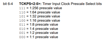
So, bringing this back to my example of a 1kHz timer, I can now accomplish it as follows:
- Set the pre-scaler to 8 (TCKPS = 011)
- Calculate the period as follows: PR = 100,000,000 / 1,000 / 8 = 12500.
12500 fits neatly into a 16-bit register, so no problems there. Do be aware that some pre-scaler values will lead to fractional numbers, which will just be truncated and lead to inaccurate timing. For example, a pre-scaler value of 64 would lead to a required PR of 1562.5.
Setting up a timer
OK, phew. Theory out the way, let's see how to do this in code:
void init_timer2(int period)
{
    T2CON   = 0x0;      // Disable timer 2 when setting it up
    TMR2    = 0;        // Set timer 2 counter to 0

    /* Set up the period. Period = PBCLK3 frequency, which is SYS_FREQ / 2, divided by the frequency we want and then divided by 8 for our chosen pre-scaler. */
    PR2 = SYS_FREQ / 2 / period / 8;

    // Set up the pre-scaler
    T2CONbits.TCKPS = 0b011; // Pre-scale of 8

    // Turn on timer 2
    T2CONbits.TON   = 1;
}
Bam, that's it! It's incredibly simple to do. Of course, now the timer is running and that's great and all but we want to use the timer for something. For that, we need to discuss interrupts.
Interrupts on the PIC32MZ
The PIC32MZ is a fast processor but it is still a single core, single threaded processor. This is important because if we are running a while() loop and our timer keeps interrupting our code every 1/1000 times a second, the PIC32MZ will leave what we are doing in the while() loop, jump to the code for doing whatever we told it to do when the timer ticks, complete that, and then jump back to the while loop until it is interrupted again. These interruptions are called interrupts, funnily enough.
The PIC32MZ has a very deep interrupt system. In short, each interrupt can be assigned a priority from 1 to 7 and a further sub-priority of 0 to 3.
A higher interrupt priority gets handled first and a lower interrupt priority gets handled later. Further, a higher priority interrupt can actually interrupt a lower priority interrupt but the reverse is not true. Sub-priorities can be used when interrupts have the same pririoty, as a further way of sub-dividing which of these interrupts is more important.
First, before we begin, you should generally enable Multi Vectored interrupt mode. This will save you many headaches when working with interrupts and you're finding they don't work and you can't work out why. It basically tells the PIC32 to allow use of a different handler for each different type of interrupt (Timer 2, Timer 3, etc). Thankfully, this is very easy to do:
INTCONbits.MVEC = 1;
The timer 2 interrupts have four important bits associated with them:
- Timer 2 Interrupt Enable (T2IE)
- Timer 2 Interrupt Flag (T2IF)
- Timer 2 Interrupt Priority (T2IP)
- Timer 2 Interrupt Sub-priority (T2IS)
Searching the infamous datasheet reveals that T2IE is in the IEC0 register, T2IF is in the IFS0 register and both T2IP and T2IS are in the IPC2 register. It is left as an exercise to the student to search the datasheet to find where the other timer interrupt bits are located :)
OK. let's re-visit that init_timer2() function from before, but this time let's enable the Timer 2 Interrupt with a priority of 3 and a sub-priority of 1.
void init_timer2(int frequency)
{
    T2CON   = 0x0;      // Disable timer 2 when setting it up
    TMR2    = 0;        // Set timer 2 counter to 0
    IEC0bits.T2IE = 1;  // Disable Timer 2 Interrupt

    // Set up the period. Period = PBCLK3 frequency, which is SYS_FREQ / 2, divided by the frequency we want and then divided by 8 for our chosen pre-scaler.
    PR2 = SYS_FREQ / 2 / frequency / 8;

    // Set up the pre-scaler
    T2CONbits.TCKPS = 0b011; // Pre-scale of 8

    IFS0bits.T2IF = 0;  // Clear interrupt flag for timer 2
    IPC2bits.T2IP = 3;  // Interrupt priority 3
    IPC2bits.T2IS = 1;  // Sub-priority 1
    IEC0bits.T2IE = 1;  // Enable Timer 2 Interrupt

    // Turn on timer 2
    T2CONbits.TON   = 1;
}
OK, that was a lot of explaining for very little code. There's one final step, writing the interrupt handler. Almost done, bear with me!
Writing an interrupt handler on the PIC32MZ
I want my timer interrupt handler to toggle pin RH0 every time it is called. Let's take a look at how I write this:
void __attribute__((vector(_TIMER_2_VECTOR), interrupt(ipl3soft), nomips16)) timer2_handler()
{
    IFS0bits.T2IF = 0;  // Clear interrupt flag for timer 2
    LATHINV = 1 << 0;   // Toggle pin RH0
}
OK, the code itself is very simple but hoo boy that declaration. Let's break it down:
__attribute__tells the compiler we are going to give it specific instructions for how to handle this function.- The interrupt vector _TIMER_2_VECTOR is defined by the include file
p32mz2048efh144.h. You can also use the IRQ number found in the datasheet directly, in this case 9. - The
ipl3softrefers to Interrupt Priority Level 3 (yes, that's a lowercase L). If you want to know what thesoftpart means, refer to the <TL;DR> below. nomips16forces the compiler to generate code using the MIPS32 instruction set and not the MIPS16 instruction set. This is required for interrupts on the PIC32.timer2_handler()is just what I named the function, you can name it whatever you want.
Inside the function itself, there are only two lines. The first line clears the interrupt flag for timer 2. If you do not clear this flag, the interrupt handler will immediately and repeatedly get called again until it is cleared. It is recommended that you clear this flag immediately, and that your code inside an interrupt handler does not take too long. Keep interrupt handler code short and simple, don't write files or anything inside an interrupt because by the time the file writing is done the PIC32MZ will have missed the timing of several interrupts and things will go pear-shaped. And that's it, interrupt handler done!
Let's take a look with an oscilloscope to see if this gives us what we want:

And there it is, just what we expect. The signal is high for 1ms, low for 1ms, high for 1ms, etc, which means it's changing at a rate of 1kHz. Unlike the FatFs disasters, it seems to have worked out this time! :)
<TL;DR>
There is a rather large problem with interrupts in general. The processor needs to temporarily pause what it was doing, jump to the interrupt handler and then go back to what it was doing. This means, of course, that it needs to first save what it was doing so it can go back to it later. In case of the PIC32MZ, this means it needs to save the contents of some important registers before it can actually call the interrupt handler. This delay is called interrupt latency. For almost all of the stuff I do, which is not time-critical, this delay doesn't make much difference but for time critical stuff it can be a huge problem. The PIC32MZ combats this by having a Shadow Register Set (SRS) that you can use to minimize this latency. Today's post is long enough, however, perhaps in the next post. Or you're welcome to Google it for yourself :)
To summarise:
- Setting it to
softforces it to use software context switching, i.e. manually save all the registers. This is the slowest option. - Setting it to
srsforces it to use the shadow register set, which is much faster. It will also crash your program if you haven't set it up. - Setting it to
autotells it to choose because software context switching and using the shadow regiter set. I've had issues with this when I hadn't set up the shadow register set so be warned!
</TL;DR>
Categories: pic32