Using Pulse Width Modulation (PWM) to play audio post
Using Pulse Width Modulation (PWM) to play audio on the PIC32MZ
Credit: I'm using an audio sample of a dog barking twice from a site called freesoundeffects for today's program. I do not know the site, I found it for the first time while looking for a free sound effect today. Thanks to the contributors of this sound effect, Partners In Rhyme.
PWM audio?
That's right, the varying pulses that we send out via PWM can actually be used to generate analog audio signals. The fidelity isn't super high but it's actually good enough to listen to music with. You may have heard of Digital to Analog Converters (DACs), chips that take digital data in (which can be thought of as square waves) and spit out analog sine waves. Let's take a look at the image from the last post again:

That's a 1ms pulse in a wave with a period of 20ms, and it was used to control a stepper motor. It's a nice square wave that goes high (logic 1, or 3.3V here) for 1ms and low (logic 0, or 0V here) for 19ms but what does that actually mean? If you were to hook up a multimeter to that output, what voltage would you expect to see? Let's calculate:
- We know the duty cycle (high time divided by low time) is 1 / 20, which gives us 0.05, or a 5% duty cycle.
- Our maximum value is 3.3V, so we need to see what 5% of that is. 3.3 * 0.05 = 0.165V
So if we attached a multimeter, we'd expect to measure 0.165V and in fact we do get that, or something very close. If the duty cycle were 50% we'd get 1.65V out, if it were 100% we'd get 3.3V out, etc. OK, so how does that help me make audio signals?
Well, let's look at a sine wave:

Yes, my drawing skills are amazing, I know. You can see that the sine wave moves up and down between 0V and 3.3V and has a mid-point of 1.65V. By using PWM, we can output these voltage levels too. The end result won't be as smooth as a sine wave, it'll be a square wave with a rapdily changing duty cycle, but to our ears it'll hopefully at least sound similar.
Outputting an audio buffer via PWM
Today, we're going to be looking at outputting a 44.1khz 8bit mono audio buffer via a PWM channel.
<TL;DR>
For converting audio clips to 44.1khz 8bit mono, I use Audacity and I Export Audio as "Other uncompressed file", RAW and unsigned 8bit PCM. I then use the bin2h utility to convert the audio file into a C-style array I can include in my program.
Be warned: bin2h excellently converts the file to an array but make sure to go into the header file and change the array type from char to unsigned char or your ears will hate you.
</TL;DR>
First up, let's set up a timer for 44.1khz. I'm going to use timer 3 today.
void PWM_init(int frequency)
{
    T3CON   = 0x0;      // Disable timer 3 when setting it up
    TMR3    = 0;        // Set timer 3 counter to 0
    IEC0bits.T3IE = 0;  // Disable Timer 3 Interrupt

    // Set up the period. Period = PBCLK3 frequency, which is SYS_FREQ / 2, divided by the frequency we want.
    PR3 = SYS_FREQ / 2 / (frequency);

    // Set up the pre-scaler
    T3CONbits.TCKPS = 0; // No pre-scale

    IFS0bits.T3IF = 0;  // Clear interrupt flag for timer 3
    IPC3bits.T3IP = 5;  // Interrupt priority 3
    IPC3bits.T3IS = 1;  // Sub-priority 1
    IEC0bits.T3IE = 1;  // Enable Timer 3 Interrupt

    OC6CON = 0;             // Turn off Output Compare module 6
    OC6CONbits.OCTSEL = 1;  // Interrupt source for this module is Timery (Which is Timer 3 for OC6)
    OC6CONbits.OCM = 0b110; // Output Compare Mode (OCM) is 6, which is PWM mode
    OC6RS = 0;              // Initially keep the signal low for the entire duration
    OC6CONbits.ON = 1;      // Turn on Output Compare module 6 (OC6)

    // Turn on timer 3
    T3CONbits.TON   = 1;
}
<TL;DR>
Firstly, you'll notice that I'm using interrupts despite stating last time that one of the advantages of PWM was that I didn't need interrupts. That is true, but let's consider what outputting 8bit audio at 44.1khz means:
- Every 22.67 microseconds (1/44100s) I need to output a byte of data
- This byte of data has a value ranging from 0 to 255, representing how long the pulse needs to remain high and after that time the pulse needs to go low
If you were to do this via a loop, you could also do this:
while (buffer_pos < buffer_length)
{
    OC6RS = buffer[buffer_pos];
    buffer_pos++;
    delay_us(23);
}
The big problem is that while we are doing this we can do nothing else in our code. It's much better to stick this in an interrupt and let the PIC32MZ process the data in the background while we do other things, like stream data from a file.
Secondly, I'm not using a pre-scaler. Why not? PBCLK3 is 100MHz, so PBCLK3 / frequency is 100,000,000 / 44100 which gives us 2268 and change. This means I don't need to use a pre-scaler in today's example.
</TL;DR>
Next, let's take a look at what I do in the Timer 3 interrupt handler:
void __attribute__((vector(_TIMER_3_VECTOR), interrupt(ipl5soft), nomips16)) timer3_handler()
{
    IFS0bits.T3IF = 0;  // Clear interrupt flag for timer 3

    OC6RS = buffer[buffer_pos]; // Output next byte to OC6
    buffer_pos++;               // Increase buffer position

    // Check that we're still in the range we want
    if (buffer_pos >= buffer_length)
        buffer_pos = 0;         // If not, restart at the beginning
}
Every time the timer interrupt calls, 1/44100 seconds will have passed and it's time to output the next byte. So, I write it to OC6RS and increment the position. After that, I check that we haven't gone past the end of the buffer and if we have I restart the sample by setting the position back to 0.
<TL;DR>
For the sake of simplicity, today's example just uses 1/44100 as a value for PR3 and outputs the 8bit value to OC6 directly. However, you may notice there's something wrong here. 8bit values range from 0 to 255 and the PR3 value is 2268. This means that for the vast majority of my output signal my output will be 0, because even the maximum value of 255 only yields a duty cycle of (255/2268) which is 11.2%. All this will change, though, is the volume at which the playback occurs because it changes the voltage output level (quite drastically). If you're seeking loudness above all else, multiply the value written to OC6RS by 2, 4 or even 8 if you so choose.
</TL;DR>
Inspection of actual audio output
Remember when I said the PWM was just outputting pulses of varying duty cycle? Let's take a look on the oscilloscope what is actually being put out by OC6:

OK, at least the frequency is what I expect it to be but that shape is pretty awful compared to a sine wave. So what I'm going to do is add a very simple low pass RC filter at the output of OC6. A low pass RC filter looks like this:
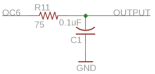
The values 75 ohms and 0.1uF come from the low pass filter formula, which is ƒcutoff = 1/(2πRC). I want the frequency to be cutoff from 22kHz, which is called the Nyquist frequency of a 44.1kHz signal. So I chose a capacitor value of 0.1uF and moved the equation around to get a resistor value of 75 ohms.
When I used the scope again to look at the point labelled OUTPUT I saw this:

"OK, that' better!" I thought and I felt very clever indeed. I remembered something about adding a "second stage" to my low pass filter and adjusted some values around like this:
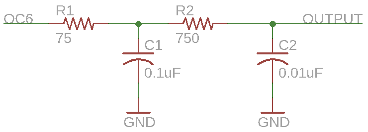
This time on the scope, I saw this:

Which, to my credit, is a lot more like a sine wave than I initially started with. However, there's a rather large problem. Or small, depending on how you look at it. These low pass filters are wonderful and I'd argue even necessary for PWM but they come with a cost. If you look at the peak-to-peak voltage levels in those three pictures you'll see:
- No filters gives me 2.830V
- Adding the first low pass filter gives me 1.850V
- Adding another stage gives me 1.160V
Yes, the average voltage isn't dropping as wildly because the waves are smoother, but the overall average voltage is still dropping considerably. This voltage drop causes the volume of the output signal to drop noticably. There are lots of other filters you can look at (perhaps an RLC filter) but that's far beyond the scope of what I want to discuss today.
IN SUMMATION: Adding a simple RC low pass filter can smooth the output and remove any unwanted high frequency whine caused by the PWM signal. Further stages do make the wave shape better but reduce average voltage level too much.
Categories: pic32