Playing MP3s using PWM audio post
Credits and disclaimers:
- Naturally, I didn't write the Helix MP3 decoder. It can be found on the Helix website.
- I made extensive use of the information provided by Microchip.
- The Helix MP3 code is based heavily on code I found by user derkling on GitHub.
- The song is Beat your competition by Vibe tracks, found in the YouTube Audio Library.
If any of the above turn out to be copyrighted, or the owner doesn't want them online anymore, please contact me and I'll change/remove them as necessary.
Update 2018-11-21: For some reason it doesn't like the way I'm converting 16-bit signed numbers to 11-bit unsigned. For now I've modified the type of playback_buffer to int because that fixes it. I've adjusted the playback buffer size to half of what it was to compensate for the extra RAM usage. It doesn't cause any exceptions so I'm not sure what's wrong. If anyone has any ideas please do let me know :)
Playing MP3s on the PIC32MZ
Ever since I started writing this site I've been wanting to write this post. In fact, almost every post leading up to this point had this in mind. For years I wanted to be able to play MP3s from my microcontroller and have seen countless solutions for Arduino and PIC but most of them use an external decoder like the VS1053b. I've also been aware of the PIC32 Helix MP3 decoder for some time but I never wanted to sit down and look at the source code because ain't nobody got time for that.
A few months ago I eventually had enough willpower to sit down and make everything work. To my surprise, I was able to get MP3s working after a few (stressful) days of tinkering. At this point, my modifications can even run on a PIC32MX170F or PIC32MX270F chip and they only run at 40MHz! The main requirements for the MP3 player are as follows:
- 28000 bytes of RAM (heap) for the decoder
- 1940 bytes of RAM for the encoded MP3 data buffer
- 4608 bytes of RAM for the decoded MP3 data
- 4608 bytes of RAM for the playback buffer
This totals 39,156 bytes of RAM needed, no problem for the PIC32MZ. Some of those sizes can be tweaked but those are the numbers I am using in my implementation. It should be noted that compiler optimisation is necessary. You need to change to O1 at least, possibly even O3 depending on your device. I found that the PIC32MX series needed O3 to work.
<TL;DR>
Compiler optimisation? If you go to the Production menu -> Set Project Configuration -> xc32-gcc -> Option categories -> Customise you can see five options for Optimisation level:
- 0 - This is the default. It's also the only option where debugging works nicely. However, it generates horribly inefficient code that almost seems intentionally bad.
- 1 - This is the level you should use if you have any timing specific code.
- 2 - Levels 0 and 1 are free but levels 2 and up require a license. Level 2 is better than level 1 but I don't use it for my little projects.
- 3 - The best optimisation level. This is required to use the MP3 decoder on the 40Mhz PIC32MX parts.
- s - This level optimises for smaller code while also trying to be as efficient as it can.
For my purposes, levels 0 and 1 are fine. I'm not writing code for devices I'm just making projects in my spare time :)
OK so then what is heap size? Heap is a term that means memory is allocated dynamically (so while the program is running) and not in the code (such as an array). The MP3 decoder uses malloc() to allocate memory for itself and thus cannot work without a heap. This has to be manually set up in your project. Go to Production menu -> Set Project Configuration -> xc32-ld -> Heap size (bytes) and type in 28000. That should be enough but if you run into random errors with some songs maybe try increasing it.
</TL;DR>
When you open the attached ZIP file, you will see two folders:
* PIC32MZ_11.X - The project itself, with all of its many files.
* SD card - This folder contains beat.mp3, which must be copied to the root directory of your SD card in order for this program to work.
The flow of the program
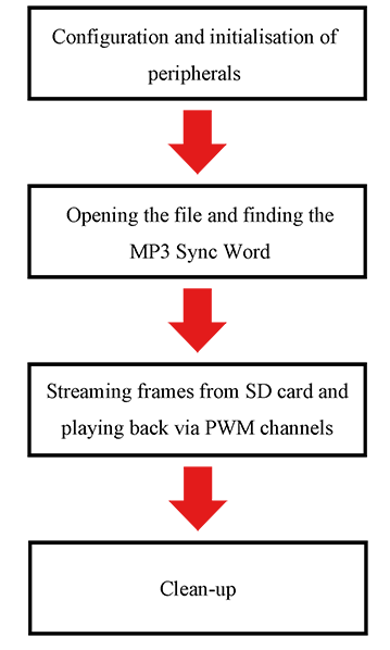
Let's take a brief look at those individually.
Configuration and initialisation of peripherals
There is one new thing here, related to SD card setup:
// Enabling internal pull-up bits to counter potential problems
CNPUBbits.CNPUB3 = 1;
CNPUBbits.CNPUB5 = 1;
I've enabled the internal, weak pull-ups on SDI2 and SDO2 to counter any potential problems others may have. I usually put 10k pull-up resistors on my physical dev boards to counter these issues and that's why I didn't get why my code was working last time. Hope this helps!
Apart from that, there's really nothing out of the ordinary here. Please bear in mind that my code uses the following settings:
- SD card is set up to use SPI2, with CS on RA0, MISO (SDI2) on RB3, MOSI (SDO2) on RB5 and Clock (SCLK2) on RG6 (SCLK2 is hard-wired and cannot be changed).
- PWM outputs are set up as follows: OC2 is connected to RC2 and OC6 is connected to RC1.
If you need to adapt this code, please bear all of those in mind. SD card changes can be made in mmcpic32.c as discussed before, but changes to the PWM outputs need to be made both in the PPS setup section in main(), that is:
// PPS for PWM outputs
RPC1R = 0b1100;         // RC1 = OC6
RPC2R = 0b1011;         // RC2 = OC2
As well as in the PWM_init() function:
OC2CON = 0;             // Turn off Output Compare module 6
OC2CONbits.OCTSEL = 1;  // Interrupt source for this module is Timer 3
OC2CONbits.OCM = 0b110; // Output Compare Mode (OCM) is 6, which is PWM mode
OC2RS = 0;              // Keep the signal low for the entire duration

OC6CON = 0;             // Turn off Output Compare module 6
OC6CONbits.OCTSEL = 1;  // Interrupt source for this module is Timer 3
OC6CONbits.OCM = 0b110; // Output Compare Mode (OCM) is 6, which is PWM mode
OC6RS = 0;              // Keep the signal low for the entire duration
OC2CONbits.ON = 1;      // Turn on Output Compare module 6 (OC6)
OC6CONbits.ON = 1;      // Turn on Output Compare module 6 (OC6)
Opening the file and finding the so-called MP3 Sync Word
Nothing out of the ordinary here either. The program attempts to open a file named "beat.mp3" in the root directory of the SD card. On success, it'll attempt to intialise the MP3 decoder like this:
// Initialise the MP3 decoder
mp3Decoder = MP3InitDecoder();

if(mp3Decoder == 0)
{
}
If the MP3 decoder could not be initialised, mp3Decoder will be equal to 0 (null) and the program will not work. If this happens, the first thing you should attempt is to increase the heap size as I mentioned earlier in the post.
From there, chunks are read from the file until the MP3 Sync Word is found. This is a special marker that marks the start of a valid frame. After that, it attempts to read the data from the frame. If the frame is valid, the first phase of MP3 reading is complete and we now have the song's frequency, number of channels and bit depth.
PLEASE NOTE: This example program will only work with 16-bit stereo MP3 files. It should be fairly easy to modify it to work with mono or other bit depths.
Streaming the remaining frames from SD card and playing them back via two PWM channels
From here, the program simply reads data from the MP3 file on the SD card into a buffer and attempts to decode the MP3 frames as they are read. It outputs the data to a playback buffer that the Timer 3 interrupt will use to output the audio data.
My program uses something called a "circular buffer" for the playback data. All this is, is an array that works as follows:
- The interrupt routine keeps track of the position it is reading from in
pb_readpos. - The main streaming loop keeps track of where it is writing in
pb_writepos. - Writing to the array is very fast on the PIC32MZ, much faster than the comparatively slow Timer 3 interrupt that operates at 1/44100s or every 22 microseconds.
- Writing to array continues until the reading position = the writing position, at which point the writing waits until the reading position has moved on and then writes some more.
- Once the writing part runs out of data to write, the program decodes another MP3 frame and starts writing again. This continues until the entire MP3 file has been played.
I prefer this system to other ones like double-buffering because there's only one array. It also writes data as soon as it can, pretty much ensuring there will be no stutters or hitches in the playback. You can easily do other things in between as the playback buffer is fairly big and can easily be made even bigger. The size is defined at the top of the code:
#define PLAYBACK_BUFFER_SIZE 2304 * 4
This provides 9,216 words of data which is four times the MP3 decoder's output buffer size. At 22 microseconds per word, is about 203 milliseconds. If your program is experiencing underrun errors and the audio is stuttering, increase this value. If you need more RAM, decrease it.
Clean-up
Once all the frames are played (or an error occurs), the very first thing the program does it call PWM_stop(). If you don't do this, the program will keep playing the last 203 milliseconds of data over and over again and nobody wants that.
After that, it closes the MP3 file handle with f_close() and frees the memory used by the MP3 decoder.
That's it for general code overview, let's take a look at some more in-depth things. This entire next section can be considered <TL;DR> :)
Things to be aware of when playing MP3s back via PWM
Converting signed 16-bit numbers to unsigned 11-bit
Most MP3s I've seen are encoded at 44.1kHz or 48kHz signed 16-bit stereo. Let's think about what that means in terms of playback.
The frequency is not a problem, we already did 44.1kHz last time. The real problem is the 16-bit signed audio. Let's take a look at our timer calculation again:
PR3 = SYS_FREQ / 2 / frequency;
Plugging in some numbers for 44.1kHz, we can see that we get:
PR3 = 200,000,000 / 2 / 44,100 = 2,267
OK, but so what? Well, 16-bit numbers can hold up to 2^16 - 1, or 65,535. Further complicating matters is that this audio is signed, meaning is uses the first bit as a +/- sign and the rest of the 15 bits as data.
However, the most resolution we can get at 44.1kHz is 11-bit (as 2^11 - 1 = 2,047). Thankfully, this still sounds pretty good. So our first order of business will be to convert that 16-bit sign data into the 11-bit unsigned data our PWM channels expect. We can do it as follows:
output_data = ((input_data + 32,768) >> 5)
<TL;DR>
Signed 16-bit audio data is represented as a wave with audio centered around 0. Unsigned 16-bit audio data is represented as a wave centered around 32,768. So effectively, all we need to do is shift the entire waveform up by 32,768 positions to shift the center-point. That's why we add 32,768.
Because this is the tl;dr section, let's refresh how signed binary numbers work again. Let's take 3,000 and -3,000 as examples and see how they look in binary.
3,000 = 0000 1011 1011 1000b
-3,000 = 1111 0100 0100 1000b
Hmmmm... what? Negative binary numbers are generally represented using something called Two's complement, which is itself a modification of One's complement. It works as follows:
- Write down the number in binary
- Toggle all the bits, changing 0's to 1's and 1's to 0's
- Add 1 to the answer
So for our example, we have 3,000:
- 3,000 = 0000 1011 1011 1000b
- Toggle : 1111 0100 0100 0111b
- Add 1 : 1111 0100 0100 1000b
Which was our answer to start with. For more information, Google Two's complement, it really isn't the focus of today's post.
Finally, we shift right by 6 bits because we want to discard the lower 6 bits and only keep the more important upper 10 bits.
</TL;DR>
Stereo audio from PWM
Thankfully, this is an easy one. You just need to set up two Output Compare modules. In my example, I've used OC2 and OC6. If you remember the first post on PWM, there is one thing you need to be aware of:
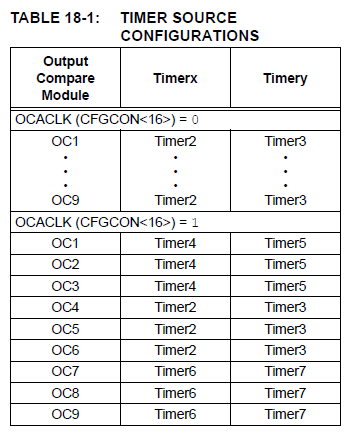
If, for whatever reason, you have set the OCACLK bit in CFGCON to 1, the Output Compare modules use different timers for their operation. As I don't do that, I don't have such an issue.
OK, good luck with that. If anybody reads this and tries it, I'll be happy to help in the comments. I realise the number of PIC32MZ hobbyists like me out there probably isn't very high but I hope it helps.
Categories: pic32