Using the PIC32MZ EF USB module in host mode post
Writing about USB MSD is fairly dry, boring stuff, so while I'm investigating USB on the PIC32MZ series, I thought I might as well try and get host mode working. Boy, what a mission. There's even less documentation on how things work, even less examples for it and there are so many quirks and weird things about it. I've finally gotten to the stage where I can connect to a device and query it (on endpoint 0), so I thought I'd share my code for anyone that may need this.
Setting up host mode
OK, here's the code I (currently) use. You'll notice it's quite different from the device mode initialisation.
void USB_init()
{
    volatile uint8_t * usbBaseAddress;

    USBCRCONbits.USBIE = 1;

    *((unsigned char*)&USBE0CSR0 + 0x7F) = 0x3;
    delay_ms(10);
    *((unsigned char*)&USBE0CSR0 + 0x7F) = 0;

    USBCSR2bits.SESSRQIE = 1;
    USBCSR2bits.CONNIE = 1;
    USBCSR2bits.RESETIE = 1;
    USBCSR2bits.VBUSERRIE = 1;
    USBCSR2bits.DISCONIE = 1;
    USBCSR2bits.EP1RXIE = 1;
    USBCSR1bits.EP1TXIE = 1;

    IEC4bits.USBIE = 0;         // Enable the USB interrupt
    IFS4bits.USBIF = 0;         // Clear the USB interrupt flag.
    IPC33bits.USBIP = 7;        // USB Interrupt Priority 7
    IPC33bits.USBIS = 1;        // USB Interrupt Sub-Priority 1
    IPC33bits.USBDMAIP = 5;
    IPC33bits.USBDMAIS = 1;
    IFS4bits.USBDMAIF = 0;
    IEC4bits.USBDMAIE = 0;

    USB_init_endpoints();

    USBCSR0bits.HSEN = 1;
    USBCRCONbits.USBIDOVEN = 1;
    USBCRCONbits.PHYIDEN = 1;

    USBCRCONbits.USBIDVAL = 0;
    USBCRCONbits.USBIDVAL = 0;

    IFS4bits.USBIF = 0;         // Clear the USB interrupt flag.
    IFS4bits.USBDMAIF = 0;

    IEC4bits.USBDMAIE = 1;
    IEC4bits.USBIE = 1;         // Enable the USB interrupt

    USBOTGbits.SESSION = 1;
}
Let's get straight to it. What the heck is *((unsigned char*)&USBE0CSR0 + 0x7F) = 0x3; and why am I doing it like that? I first saw this code in Harmony and I wondered the same thing. First off, what does it mean? For that, we need to take a look at the datasheet:
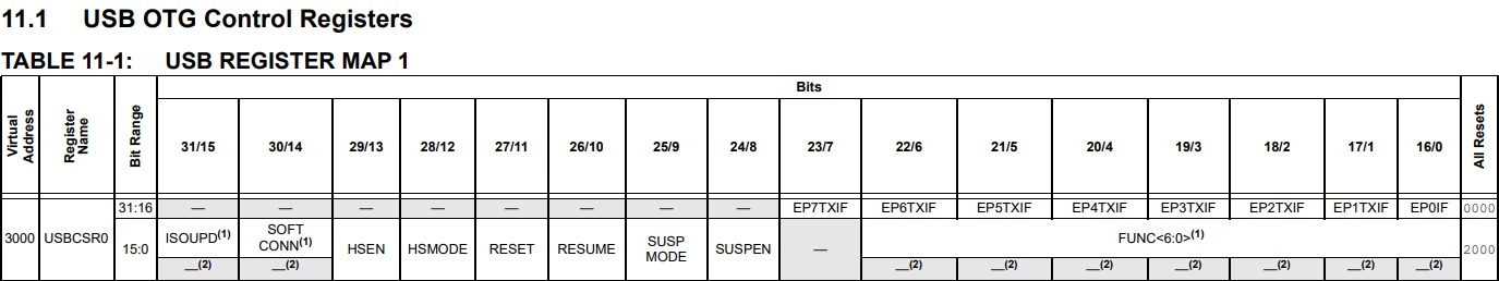
The important piece of information is the address of USBCSR0, which is listed as 3000 (which is actual hexadecimal, so 0x3000). So to get the target address of that piece of code, we need to see what's at 0x3000 + 0x7F, or 0x307F:

Side note: The datasheet has split USBEOFRST into USB and EOFRST, so you can't search for USBEOFRST in the address list. Way to go Microchip!
OK, so USBEOFRST, the register controlling "USB END-OF-FRAME/SOFT RESET CONTROL" starts at 0x307C. So the first byte of the 4-byte register is at 0x307C, the second byte at 0x307D, the third at 0x307E and the fourth at 0x307F, which is the address we are looking for. Setting this to 3 will set the NRST and NRSTX bits.
But what do those bits do? Let's look further down in the datasheet:
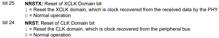
OK, so it resets some clock or other. Point is, if you don't reset this, USB host will not work at all. In Harmony code I saw, Microchip describes it as a "workaround for an error in the PHY", though I cannot find this in any errata anywhere.
So we know what that line of code is doing, but why are we doing it like that? Surely we can go:
USBEOFRSTbits.NRST = 1;
USBEOFRSTbits.NRSTX = 1;
and have the same result? I mean, surely, right? XC32 even has the bit definitions there and everything. And yet, it doesn't work. It sometimes seems to, but most often not. There are a few registers relating to USB that you have to access indirectly like this or nothing works at all! If anybody knows why, I'd sure appreciate a message. Anyway, Harmony does it like this and for once it makes sense why they did it in this way.
So we enable interrupts turn on the "soft reset" bits, wait 10 milliseconds, turn them off (which turns the USB clock back on) and then disable interrupts again. Why enable them to disable them straight away? I don't rightly know, this is what Harmony seemed to do and it took me a week of solid trying to get anything to work, so maybe I'm just superstitious at this point! Let's take a look at the next block:
USBCSR0bits.HSEN = 1;
USBCRCONbits.USBIDOVEN = 1;
USBCRCONbits.PHYIDEN = 1;

USBCRCONbits.USBIDVAL = 0;
USBCRCONbits.USBIDVAL = 0;
Enable High Speed mode by setting HSEN to 1. Enable the USB ID override enable bit by setting USBIDEOVEN to 1. Enable monitoring of the PHY ID by setting PHYIDEN to 1 and then set USBIDVAL to 0 (0 = host, 1 = device). The value of USBID is very important for the USB module, I've started using USB-C connectors on my boards, and they don't have a USBID pin.
So I control this via software now. Please note that you should also enable the pull-down for pin RF3 (the USB ID pin) like this:
CNPDFbits.CNPDF3 = 1; // Pull down to ensure host mode
to ensure the USB ID pin's value is 0. I don't know if you have to do this even with USB ID override enabled, but like I said it took a week of pulling my hair out before I finally got this to work and I didn't mess with it further yet.
The final piece of the puzzle is setting USBOTGbits.SESSION to 1, which starts a session with an attached device. In device mode, we had to set USBCSR0bits.SOFTCONN to 1, but that is not the case in host mode.
The program flow after intialising the USB port
This part again took a while to get my head around, mostly because I didn't know much about USB before I started this. The flow, from what I can see, seems to be:
- Once a device is plugged in, a Device Connection Interrupt (enabled by setting
CONNIEto 1 earlier) will be thrown and your ISR needs to catch this. - When a connection interrupt is thrown, you need to tell the device to reset itself. This is where the device will set up its endpoints so this is very important!
- After that, you can communicate with the device on endpoint 0.
OK, easier said than done right? Right.
Catching the Device Connection interrupt
Let's take a look at the part of my USB ISR in question:
    unsigned int CSR0, CSR1, CSR2;

    CSR2 = USBCSR2;

    RESETIF = (CSR2 & (1 << 18)) ? 1 : 0;

    CONNIF = (CSR2 & (1 << 20)) ? 1 : 0;
Why do it like that? If you'll remember from device mode, once you read USBCSR2 (or USBCSR0 or USBCSR1) all the interrupt flags will be reset! You need to store the values beforehand if you want to check for multiple interrupts, which we do!
Telling the device to reset itself
Fairly straightforward, thankfully:
USBCSR0bits.RESET = 1;
delay_ms(100);
USBCSR0bits.RESET = 0;
delay_ms(100);
You don't need to wait 100ms, this code is still in the early stages so I'm playing around to see how long I have to wait. It works with a 100ms delay. Again, this will tell the attached USB device to reset its USB stack and initialise its own endpoints. Depending on the device, this may be the difference between it working or not.
Communicating with an attached device on endpoint 0
Here's where the real fun begins! This is pretty much the opposite of device mode in that instead of receiving queries and answering them, we will be sending the queries and reading the replies. The difference is, we now need to set slightly different bits to communicate. These endpoint 0 packets, called setup packets, are special and different from packets on the other endpoints. Let's take a look at my code for sending on endpoint 0:
void USB_EP0_send_setup(unsigned char *buffer, uint32_t length)
{
    int cnt;
    unsigned char *FIFO_buffer;

    FIFO_buffer = (unsigned char *)&USBFIFO0;

    for (cnt = 0; cnt < length; cnt++)
    {
        *FIFO_buffer = *buffer++; // Send the bytes
    }

    *((unsigned char*)&USBE0CSR0 + 0x2) = 0xA;
}
First off, the length of these setup packets seems to always be 8 bytes, and some devices can only handle 8 bytes at a time. So be warned! In device mode, we needed to set TXPKTRDY to 1 but here we need to set both TXPKTRDY and SETUPPKT to 1. This tells the PIC32MZ USB hardware to send a setup token instead of an OUT (i.e. from host to device) token. Some requests, for
example assigning an address to the device, will not require any data from the device. However, if the device does need to reply, what do we do? Let's take a look at my code for requesting and reading a device descriptor:
void USB_HOST_read_device_descriptor(unsigned char *buffer)
{
    int received_length;
    int bytes_to_read;
    int buffer_index;

    bytes_to_read = 0x12; // 18 bytes for device descriptor
    buffer_index = 0; // Start at the beginning

    // Send descriptor request
    USB_EP0_send_setup(USB_DEVICE_DESCRIPTOR_REQUEST, 8);

    // Wait for the TX interrupt to fire, indicating it was sent
    USB_EP0_IF = 0;
    while (USB_EP0_IF == 0);

    // Once it is sent, request a packet from the device
    *((unsigned char*)&USBE0CSR0 + 0x3) = 0x60;

    while (bytes_to_read > 0)
    {
        USB_EP0_IF = 0;
        while (USB_EP0_IF == 0);
        received_length = USBE0CSR2bits.RXCNT;
        USB_EP0_receive(&buffer[buffer_index], USBE0CSR2bits.RXCNT);

        buffer_index += received_length;
        bytes_to_read -= received_length;
        if (bytes_to_read > 0)
            // Request another packet (set REQPKT)
            *((unsigned char*)&USBE0CSR0 + 0x3) = 0x20;
        else
            // The read is done, clear STATUS bit and REQPKT bit
            *((unsigned char*)&USBE0CSR0 + 0x3) = 0x0;
    }
}
As the comments state, we send the request and then we wait until the TX interrupt fires, indicating that we have actually sent the packet. Then, vitally, we need to set some more bits to tell the USB hardware we want a packet from the device. We do this by setting the bits STATPKT and REQPKT to 1. Now the USB hardware will actually request an IN packet (i.e. from device to host transfer).
Once it arrives, an interrupt will fire (EP0IF will be set), indicating we have received some data. We can read this data from EP0 at usual with the following code:
void USB_EP0_receive(unsigned char *buffer, uint32_t length)
{
    int cnt;
    unsigned char *FIFO_buffer;

    // Get 8-bit pointer to USB FIFO for endpoint 0
    FIFO_buffer = (unsigned char *)&USBFIFO0;

    for(cnt = 0; cnt < length; cnt++)
    {
        // Read in one byte at a time
        *buffer++ = *(FIFO_buffer + (cnt & 3));
    }

    USBE0CSR0bits.RXRDYC = 1;
}
This is exactly the same as the reading procedure for device mode. Now, depending on the device, it may only be able to send 8 bytes at a time. For example, my PlayStation 5 controller (no, I don't have a PS5, just a controller :)) can send 64 bytes at a time. My Logitech Unifying receiver can only send 8 bytes at a time. For this particular request (get device descriptor), I need to receive 18 bytes. This means that the
PS5 DualSense controller will send the reply all at once, but the Unifying receiver will split it into 3 packets of 8 + 8 + 2 bytes in length. If you are still expecting more bytes, you need to set the REQPKT bit again. If you are done receiving, you must clear both the STATUS and REQPKT bits.
While this all seems perfectly straightforward in hindsight, believe me when I say finding this all out without any documentation was a real pain in the butt.
That's all for today. Next time I'll either continue the MSD posts or upload something on HID. Hope this helps!