UART and Peripheral Pin Select (PPS) on PIC32MZ post
How to use the PPS functionality and how to set up the UART
It's been a while, so time to blog about something worthwhile! A lot of the cool peripherals (devices) on the PIC32MZ aren't assigned to specific pins, you can choose between a set of pins on which to place them. For today's example, I will be looking at how to set up the PPS pins to give me UART port 5 on pins RF0 and RF1. There are two pins that we want, the receive pin (RX) and the transmit pin (TX). So let's go look at the datasheet and see what it says.
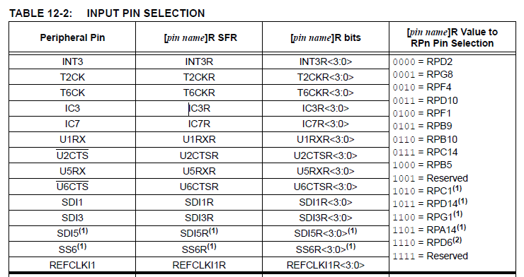
These are some of the input pins we can set up. We are looking for U5RX, the RX pin for UART number 5. As you can see, it's on the left. The pins on the right are the possible pin numbers we can place that pin on. I want to place it on pin RF1, which is also called RPF1. Looking on the right, I can see that the code to do this is 0100. So now, we go to the code and set U5RX to 0b0100, like this:
U5RXR = 0b0100; // RF1 = U5RX
Simple, if you know how. But wait, there's more! Because this is now an input pin, we need to set up the TRISF register to make that pin an input too.
TRISFbits.TRISF1 = 1; // Make RF1 an input
OK, now let's set up the TX pin. Let's look at the datasheet again.
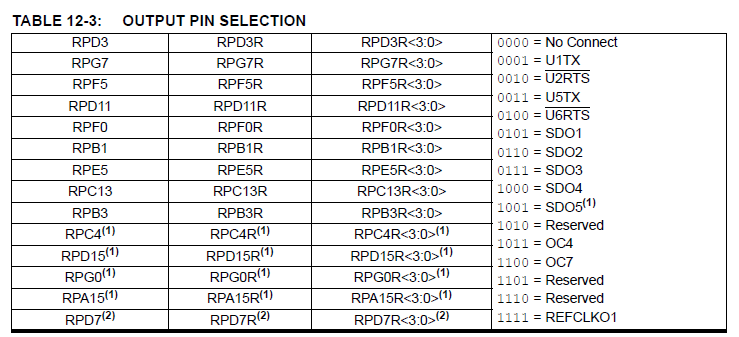
For the output pins, the peripherals are listed on the right and the possible ports on the left. We can see on the right that U5TX has a code of 0011, and as we want it on pin RF0 we set it up as follows:
RPF0R = 0b0011; // RF0 = U5TX
OK, now we've assigned the UART 5 peripheral to pins RF0 and RF1, it's time to initialise it. In this example, I want to set it up at a baud rate of 38400bps so I can communicate with my FTDI cable connected at those pins. I like doing this for debug logs and just communicating with the PC in general. Unfortunately, when we look at the datasheet and the UART section we get to read this:
"This data sheet summarizes the features of the PIC32MZ EF family of devices. It is not intended to be a comprehensive reference source. To complement the information in this data sheet, refer to Section 21. “Universal Asynchronous Receiver Transmitter (UART)”(DS60001107) in the “PIC32 Family Reference Manual”, which is available from the Microchip web site (www.microchip.com/PIC32)."
Wonderful, so we google DS60001107 and find the UART datasheet and down the rabbit hole we go. Nothing is quick and easy to do on the PIC32. Let's look at the speed calculation formula:
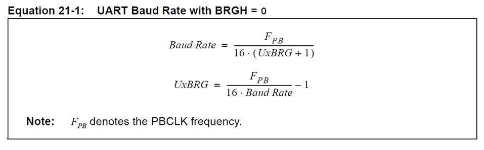
Very long story short, the UART peripherals are run off of Peripheral Bus Clock 2 (PBCLK2), which we set to 100Mhz in the previous blog post. There is a "standard speed" mode and a "high speed mode". The standard speed mode has a maximum speed of (PBCLK2 / 16) which is 6.25Mbps in our example. The high speed mode has a maximum speed or (PBCLK2 / 4), which is 25Mbps for us. As I'm using a much, much slower speed I'm going to be setting it up in standard mode. Here's the code to initialise UART 5 at 38400bps:
void UART_Init()
{
    int pbClk;

    pbClk = SYS_FREQ / 2; // Our PBCLK2 divider was set to 1, so PBCLK2 is exactly half the speed of the system clock, or 100Mhz

    U5MODE = 0; // Set UART 5 off prior to setting it up
    U5MODEbits.BRGH = 0; // We want standard speed mode. Not necessary as we just set U5MODE to 0 so this is just for explanation's sake
    U5BRG = pbClk / (16 * 38400) - 1;// This is the formula straight from the datasheet
    U5STA = 0; // Disable the TX and RX pins, clear all flags
    U5STAbits.UTXEN = 1; // Enable the TX pin
    U5STAbits.URXEN = 1; // Enable the RX pin
    U5MODEbits.PDSEL = 0; // PDSEL controls how many data bits and how many parity bits we want, this is the default of 8-bit data, no parity bits that most terminals use
    U5MODEbits.STSEL = 0; // STSEL controls how many stop bits we use, let's use the default of 1
    U5MODEbits.ON = 1; // Turn on the UART 5 peripheral
}
Phew. That's actually the hardest part done. Now we can immediately start writing data to UART 5 by writing to U5TXREG, like this:
char c;
c = 'A';
U5TXREG = c;
But there's a much cooler and easier way to do this that allows us to use printf. We need to overwrite the _mon_putc function, which is thankfully really easy:
void _mon_putc (char c)
 {
   while (U5STAbits.UTXBF); // Wait til current transmission is complete
   U5TXREG = c;
}
And that's it! Now we can use printf to send data directly to the serial port UART 5. Remember, when connecting the FTDI cable you need to connect the FTDI's TX pin to the PIC32's RX pin and the FTDI's RX pin to the PIC32's TX pin. I've attached a very basic, but working, program that outputs a counter to the serial port every second.
Here's the code Have fun!
Categories: pic32